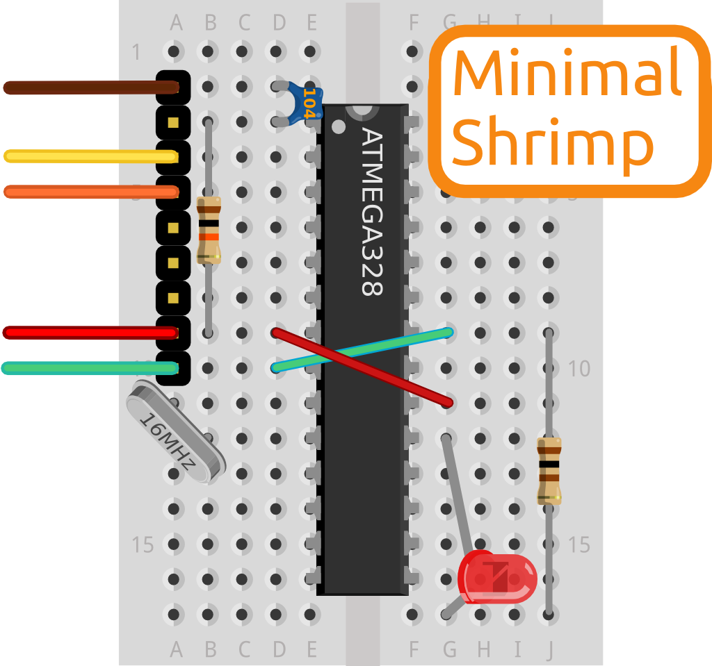
First, we need all of the components shown in this picture taken from the Shrimp website:
The materials used are the following:
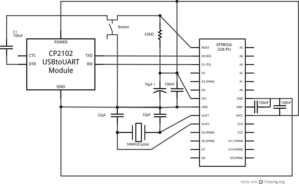
(1) CP2102 USB to UART converter (from ebay)
(1) Ceramic capacitor, 100 nF (Also labeled as 104, meaning it is 10 0000 picofarads; this is number 10 plus four zeros after it, making 100,000 picofarads equals to 0.1 uF)
(2) Ceramic capacitor, 22 pF (labeled as 22)
(1) Crystal Oscillator (rated at 16.000 MHZ)
(1) Resistor (rated at 10 Kohm, but I went for the color shown in the pic: brown, black, orange, gold)
(1) Atmega328P-PU (found on ebay, came already with Arduino UNO Bootloader; I know you need to program your Atmega to use it as an arduino, or else its only a piece of plastic)
(3) wires, to make connections
NOTE: In order to test the arduino, I had to connect an LED to it, but I'll show you later.
First I built the Shrimp. I do not know if these ceramic capacitors have a direction, so I just placed them all looking at me, just like in the picture. The crystal oscillator is also sitting just like in the picture. The resistor has not direction whatsoever.
My finished product looks like this:

See that green LED? and the wire going into the negative side of the LED? well, this is what I added in order to test it. the LED is going into D13 and to negative. The yellow wire goes from GND to the LED's negative side.

After everything was built (except the LED part) I tried to upload a program to the Shrimp. Note that in the shrimp webpage they tell you to use Arduino IDE as the programming tool. Im assuming you cant use the same as the arduino UNO, but im not sure.
After I did all of this, I had the problem where I was not able to upload a simple file to the Shrimp. I was getting the error: avrdude: stk500_getsync(): not in sync: resp=0x30
The Arduino IDE was also trying to connect through COM3. This error could've been due to two reasons: The Atmega328 did not have the Arduino Bootloader installed (as promissed from the ebay seller) or I did not have the drivers for the UART converter. Needless to say, my computer was not recognizing my Shrimp. It would try to install the drivers but could not. Windows tried to help me in every way but failed.
My computer is running Windows Vista, and it didnt have the drivers for the USB to UART converter. I had to go to the webpage and download it (Silicon Labs). The actual link to the driver is the this one.
After installing the driver, the Arduino IDE, when trying to upload the program (by the way, this is the program) was still trying to upload through COM3. After the driver was installed, COM15 was also available, so I switched to it and Arduino IDE uploaded my simple LED program to my Shrimp.
Today I am a happy camper. I hope this is of some use to someone out there.
Update: 07/08/2013
I have soldered the Arduino onto a board and it looks nice. I purchased all of the items from ebay except for the board which I got from my local Radio Shack. I just wanted to show it here. Also, I want to mention that I want to build another one with the board spray painted Arduino blue, and with a little logo or something to make it stand out. I will update it here if I ever do.
Also I want to mention that for being my first time soldering something this complex onto a board, I did a good job!
These are the pictures of the board:


