Tuesday, April 21, 2020

Datsun Head Bolts Torque Specs and Sequence

The information on this page applies to the Datsun L16, L18, and L20B engine.

The following describes the location of the short and long cylinder head bolts
There are 10 Head Bolts in total; Long bolts and Short bolts

REAR OF ENGINE
short        long
short        long
short        short
short        long
short        long
FRONT OF ENGINE

The following describes the Loosening sequence for the engine.

LOOSEN
REAR OF ENGINE
2         1
6         5
10       9
8         7
4         3
FRONT OF ENGINE

Loosen the bolts gradually in the sequence shown. Do multiple passes and start with 1/8 of a turn for each bolt to ensure proper removal.


The following describes the torque sequence and torque specs for the engine.

TIGHTEN
REAR OF ENGINE

10        9

6          5

2          1

4          3

8          7

FRONT OF ENGINE

Torque all bolts to 20 ft-lb, first pass
Torque all bolts to 40 ft-lb, second pass
Torque all bolts to final 60 ft-lb, third pass
Torque all bolts to 60 ft-lb, fourth pass
Torque all bolts to 60 ft-lb, fifth pass

Friday, August 19, 2016

Datsun L16 intake manifold vacuum port plug size

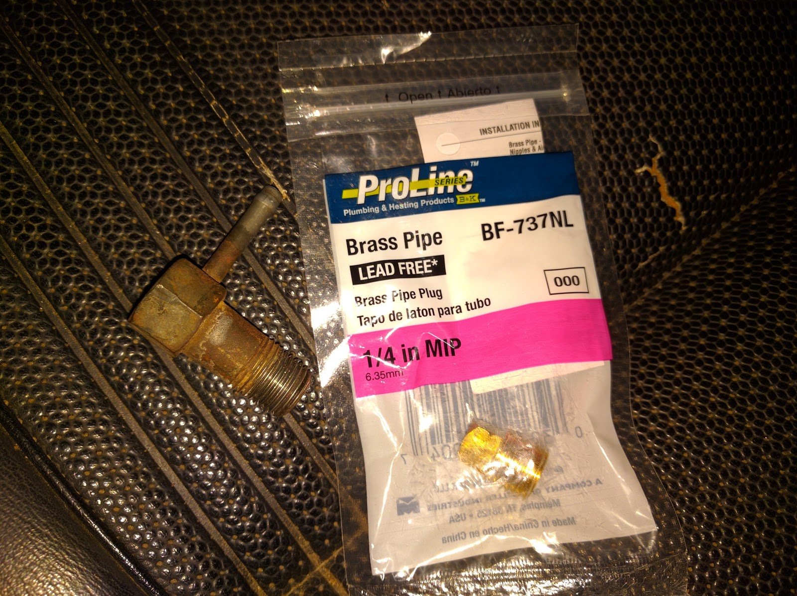
The thread size for the L16 intake manifold vacuum port size is shown in the following picture:

The vacuum adapter shown is what is going to be replaced.

Wednesday, August 10, 2016

Carburetor on an l16 510 wagon

Update:
Yesterday I made my own carburetor base gasket. It didn't work. The carb has large vacuum leaks around the base. The motor doesn't drop below 1600 rpm at idle.

Update 08/14/2016:
The carburetor that I was using is a 32/34 Weber downdraft carburetor. This needed an adapter plate and the carburetor is NOT a direct bolt on as I had need told in the past. The carburetor did run all the time but it ran rough.
I ended up installing a Weber 32/36 with manual choke and it worked so I am keeping it now.

This is the adapter plate that was needed. This particular one only fit the 32/36.

Also, Autozone sells a gasket that fits the stock intake manifold. It's for a 1977-1979 Datsun 200sx.
The following gasket is the one that works on L series motors. The part number is G31154:


Monday, July 4, 2016

Replacing A Freeze Plug

This is a quick and simple explanation on how I replaced and installed freeze plugs on my L16 motor in my Datsun 510 wagon.

Tools needed to remove a freeze plug:
-an iron mallet
-a sturdy bolt or something with a tip of about the same width. The bolt works great.
-pliers. I used water pump pliers and it was easy enough.
Hit the freeze plug on one point near the edge. This will drive this side in and the freeze plug will become free. pull the plug out with the pliers.


To insert the new plug back in:
-sheet metal hammer with round head.
-iron mallet


place the freeze plug where you want it to go in and put the sheet metal hammer inside of the freeze plug. hit the sheet metal hammer with the iron mallet and drive the freeze plug in little by little. Turn the sheet metal hammer to drive the freeze plug in on different points around the plug.


I was told that a socket that fits inside of the freeze plug works well, but the one in the pictures (29 mm) fits tight, as opposed to the sheet metal hammer. it is difficult to insert the plug with the socket shown.


Saturday, May 14, 2016

1975 Datsun 620 tranmission seal

This post is about the transmission seal that I used on my 1975 Datusn 620 with an  L20B and a 4-speed transmission.

There were two seals available at the auto parts store; a black one and a red one. My 620 came with a black transmission seal, but I purchased both to compare the new ones to the old one.


Here is a picture of the two new seals on top of their respective boxes. The old seal is without a box.


Here is a picture showing the thickness of the seals:


I had installed the red seal even though the black seal was installed. I thought the red seal was OK to use because it still fit, but I was wrong. I had not seen the black seal at the auto parts store and was not aware it was available. When I went back to the store to fix the leaking newer seal, I found the red and the black seals available. I purchased both and luckily I was able to compare the original seal to the two seals that I purchased. I removed the red seal that I had installed and I installed the black seal shown on the picture. I assume that this will keep the output shaft from leaking, but it is no warranty.

These pictures are of the seals next to each other:


Saturday, April 30, 2016

Datsun 1972 ball joint


This figure shows  two different types of Ball Joints.
FA2026 is an 11mm thread Ball joint. It is smaller in shaft diameter compared with FA1044.
The following pictures show how I installed FA2026 on my '72 wagon. This was not a great set up as I had to tighten it a lot and required a lot of work. I uninstalled it after I realized that I was using the wrong ball joint.


This picture shows a washer installed underneath the nut. This is how the 11mm thread ball joint was installed after it was completely tightened up.


This picture shows the 11mm ball joint being tightened down. A harmonic balancer tool was used to help install the ball joint. Again, this was the wrong ball joint to install on a '72 510 wagon.
This note from the autoparts store shows prices for parts that I need to purchase to upgrade my front suspension system.

The correct ball joint for my 510 is the 14mm ball joint.

1972 Datsun 510 Wagon 4-speed transmission

The following are the part numbers provided by a Ratsuner regarding the part number for a Back-up light switch for a 1972 Datsun 510  Wagon with a stock 4-speed transmission mated to an L16 engine.


Wednesday, March 9, 2016

Wednesday, October 14, 2015

Datsun 510 KA24 Engine Swap

Datsun 510 KA24 Engine Swap


WARNING! BEFORE YOU CONTINUE READING... THIS IS NOT A HOW TO. FOR NOW AND UNTIL NEXT NOTICE THIS IS SOMEHOW WHAT I PLAN TO DO TO MY 510 (ITS NOT DONE YET). PLEASE FEEL FREE TO GIVE ME YOUR INPUT.

(UPDATE 04/28/2016)

I got a good deal on a KA24DE with EVERYTHING for a swap. It came out of a 240sx but I'm unsure of the year. I need to adapt it to my 510. 

After hours of searching, I have found a very promising webpage with a list of stuff that I will need. the list is here:
http://www.the510realm.com/viewtopic.php?f=31&t=12697

And you guys should check out this guy's build:
http://community.ratsun.net/topic/55383-ka24de-datsun-510-build/


What I know:

Engine:
I have a KA24DE.
A KA24E can work too. These engines can be used off Nissan's 240SX and Nissan's D21 Pickup. The Nissan Altima or any Front Wheel Drive vehicle needs extensive modifications to fit a RWD Datsun, and to me they are not an option.

Transmission:
I have a 5 speed transmission which was originally mated to my KA24DE.
The transmission has to be out of a Rear Wheel Drive vehicle. I have read that the pickup transmissions are different from a 240SX transmission but I believe either one will work. A main difference is the way the starter is mounted.

Driveshaft:
I only have a 510 driveshaft.
Maybe just shorten it.

Differential:
I only have the stock differential. It will stay the same until the stock one blows up. The stock differential is an R160. To learn more about Datsun Differentials, read this:
http://forums.hybridz.org/topic/49194-differential-cv-lsd-hp-torque-r160-r180-r200-r230-diff-mount/.

Motor Mounts:
The original KA24 motor mounts and the original L16 motor mounts welded together should work.

Wiring:
I have a wiring set which came with my KA24DE.

Radiator:
I have a KA24DE radiator.

Radiator Hoses:
I havent looked into it yet.

Engine Crossmember:
I knowthe 510 crossmember has to be flipped. Some aftermarket cross members are available but these appear to be more expensive than cutting the original one and flipping it.

Transmission Crossmember:
I havent looked into it yet.

Z22 block with L-series head?
This is no longer an option. Read this for more info on the Z22 build:
http://newprotest.org/projects/510/jasonGray.pl

KA block with a KA head and a carburated intake manifold.
This is not an option.
I saw an KA24E carbureted intake at the junk-yard in a 720.

Stock internals:
According to this web page
https://en.m.wikibooks.org/wiki/Nissan_240SX_Performance_Modification/KA24DE_and_KA24E/TurbochargingStock
internals can make 350+ HP. The following are specs for parts according to the web page:

Pistons - Good for approx. 275-300 hp
Rods - approx. 400 hp
Crank - Indestructible
Valvetrain - No known issues
Head Gasket - approx. 320 hp WITH A GOOD TUNE (see below)
Head Studs - approx. 300-320 hp

Another webpage that I will be reading is

www.ka-t.org/index.php?sid=a424d865466148ce5ac8aa7e294f6425


Friday, November 29, 2013

While installing my new Weber 32/36 carburetor on my 1975 Datsun 620 I encountered various problems once the Weber was fully bolted down. One of my problems being the vacuum system. I have a charcoal canister that is completely unknown to me and has four hoses coming out of it. My questions were "what is this?" and "what does it do?".

Here is a picture of the canister:
de smog, charcoal canister
Figure 1: Charcoal Canister
The colors are (Figure 1), from left to right, or the passenger's side moving to the driver's side are: white, blue, green, and yellow (yes, yellow, although it is a faint yellow). 
The white color is labeled CARB
The blue color is labeled FUEL TANK
The green color is labeled PURGE
The yellow color is labeled DIST VC

The CARB vacuum line need to be cancelled.
The FUEL TANK vacuum line is connected to the line on the driver side of the vehicle that "breaths back" in to the fuel tank.
The PURGE vacuum line is connected to the intake manifold's "small nipple".
The DIST VC vacuum line is connected to the Weber's vacuum line.

The following picture are of my system:
Figure 2: Small nipple on intake manifold
Figure 2 shows the "small nipple" on the intake manifold, by the disconnected vacuum line. This is where the PURGE vacuum line is connected to.
Figure 3: Weber 32/36 vacuum line
Figure 3 shows the one and only vacuum tube coming out of my Weber 32/36 electronic choke carburetor. This line is where the DIST VC vacuum line from the canister connects to.


Furthermore, these are some webpages that show how to tune the Weber 32/36 Carburetor


Tuesday, November 5, 2013

1978 Datsun 620 pickup truck

This is a picture of my most recently aquired 1978 Datsun pickup truck


It is another possible project now. And its a king cab!

Saturday, August 24, 2013

How to install a Carburetor adapter plate for a Weber 32/36 on a Datsun 620 L20B engine

I was wondering which direction to install the adapter plate that came with my K662 WK663 Weber Carburetor kit.

I can either install it with the notches facing away from the engine or the notches facing towards the engine:
Notches facing away from the engine
Notches facing towards the engine
If anybody knows please let me know.

This is a useful resource page for webers.

The following is about my installed Weber carburetor. I can't remove the studs anymore and it is overflowing. I need help.


How to connect the Vacuum lines?


Wednesday, August 14, 2013

Disassembling of a Hitachi carburetor for a 1975/1973 Datsun 620 truck, DCH340

This post is to document the disassembling of a carburetor for my 1975 Datsun 620 truck. I am assuming I currently have in my possession a Hitachi DCH340 Carburetor that was originally equiped on a 1973 Datsun 620 truck.
I purchased the 1975 Datsun 620 truck with an unknown carburetor installed and running. There are no numbers on the carburetor for me to cross reference it to a part. I ended up buying a used one from a wrecking yard and I removed it from a 1973 Datsun 620 truck. After doing some research I concluded that I needed a carburetor gasket kit for a 1973 or 1974 Datsun 620. I purchased the one for a 1973. Please view this post for information on how I got to this conclusion.

NOTE: I will be giving some parts wrong names (to the best of my habilities), but close to what I want to describe in the pictures. I am new to carburetors so if you read any misleading names or information please let me know.

1973 Datsun 620 carburetor
Figure1: Carburetor side view A
 In figure 1 two main parts are facing towards the camera: the carburetor choke pull off, and a temperature/pressure operated valve (of some sorts, please give it a name, evaporator perhaps?). There is also an idle solenoid attached to it.
Figure 2: Carburetor side view B
 In figure 2 the fuel filter inlet tube, fuel bowl (screen), and replaceable pump (on the left) are visible facing the camera.

Figure 3: Carburetor side view C
 In figure 3 the throttle linkage is visible. This linkage is composed of a main bracket directly attached to the top cold starting butterfly (throttle used for cold starts). It also has a thick piece of wire attached to the main bracket on the far left, a spring pulling the main bracket down, the replaceable pump on the far right. An adjusting screw is visible below the main bracket, on the bottom piece of the carburetor. Also, note that this bottom piece, or "feet", have to vacuum tubes coming out of it. One is plugged, and the other one runs somewhere to the engine.
Figure 4: Carburetor side view D
 Figure 4 shows the diaphragm chassis or enclosure, the choke pull off (looks like a fuel pressure regulator on modern cars), and the automatic (electric) choke.
Figure 5: Carburetor top view
 Figure 5 shows the top of the carburetor. Nothing very special here.
Figure 6: Linkage for throttle E
 Figure 6 shows throttle E shaft attachments. I am calling throttle E the throttle plate attached to the throttle shaft viewed here, the one attached to the bracket where the throttle cable attaches to. Also, in this picture one of the adjusting bolts is visible.
Linkage F will be the one where the the diaphragm link attaches to.
Figure 6-a
 Figure 6-a shows another view of the throttle shaft E attachments.
Figure 7: Lock for the Main Bracket
 This pictures show the parts that came off the main bracket throttling shaft, the shaft where the main throttling bracket pivots on. It shows the parts and the order in which they were removed.
Figure 8: Throttling linkage, thick wire parts
 Figure 8 shows the order in which the parts removed from the thick wire link were removed in. This thick wire link is also attached to the main throttling bracket on its left hand side which is out of view.
Figure 9: Throttle shaft E disassembled parts
Figure 9 shows the disassembled parts from throttle E shaft in the order in which they were removed. This also shows the bottom of the carburetor, or its "feet".
Figure 10: Throttle E shaft
Figure 10 shows the shaft E for the throttle having more parts inside. They do not stop at part 6 as shown in figure 9. Also the shaft where the diaphragm link is attached to is also shown.
Figure 11
In figure 11 the "feet" (bottom) of the carburetor assembly is visible. Also, note that part 6 on the piece of paper has a direction, in and out, where "in" is going into the assembly.

Figure 12: Solenoid valve
Figure 12 shows the Anti-dieseling solenoid valve. This is the valve or long nut that has a wire at the tip. This also shows the link that goes from the electric choke to another shaft that goes to the carburetor's "body". This link looks like a thick metal wire.

Figure 13: Automatic choke link
Figure 13 shows the automatic (electric) choke link being disassembled. Note that there are also another two or three pieces still attached to the throttle shaft E, but we won't worry about these yet.
Figure 14: Parts disassembled from automatic choke link
Figure 14 shows the parts removed from the shaft that holds one end of the automatic choke link. These are also shown in the order in which they were removed.
Figure 15: Parts removed
Figure 15 shows the parts removed from the automatic choke and the other three pieces left behind on the throttle shaft E. These are also shown in the order in which they were removed.
Figure 16: Diaphragm link attachment
Figure 16 shows the diaphragm linkage on the carburetor. Note the short shaft on the linkage. The spring pictured in Figure 15 is attached through a hole to this short shaft coming out of the bracket.
Figure 17: Choke pull off
Figure 17 shows the choke pull off and the point where this one is attached to another link.
Figure 18: Diaphragm assembly
Figure 18 shows the bolts and diaphragm assembly corresponding to the diaphragm assembly.
Figure 19: Calibration mark
Figure 19 shows a small mark on my automatic choke. I did not put much attention to it at first, but I am now assuming this is the original position of the mark with respect to the line where the pen point is touching. I believe you are supposed to adjust this knob to either rich or lean fuel by loosening the bolts and then turning the knob. Note that here the bolts are already loose, which means that this mark could be off, but its a starting point.
Figure 20: Automatic choke, removed
Figure 20 shows the inside of the automatic choke once it is removed off the carburetor "body". If you've been reading "head", "body", and "feet" throughout the article, it refers to the three big parts remaining of the carburetor once everything else has been removed. I will show a picture later.
Figure 20-a: small beads
Figure 20-a shows small beads inside the automatic choke that were inside when I opened it. I don't know what they are or why they were inside, but I accidentally dropped them all to the floor. I was not planning on leaving them in there anyways.
Figure 21: Automatic choke link
Figure 21 shows the automatic choke link connected at the bottom of the remaining housing part for the automatic choke. I believe this link had only a pin through its eye when I took it off.
Figure 22: Choke pull off link
Figure 22 shows the link connecting the choke pull off and the automatic choke. Although it looks like a washer, I believe it only has a pin at the end of the automatic choke. Also note that the link from Figure 21 comes out of the hole to the right of the one shown in Figure 22, on the same bracket.
Figure 22-a: Automatic choke link
Figure 22-a shows the link connecting the automatic choke and the choke pull off.
Figure 23: Automatic choke holders
Figure 23 shows the three small brackets or holders holding the automatic choke in place so that its knob does not move to a more rich or more lean fuel. These should be installed concave down, as it reads on the paper.

Figure 24: Choke pull off
Figure 24 shows what is left of the choke pull off before disconnecting the vacuum line to remove the entire assembly.


Figure 25: Replaceable valve
Figure 25 shows the replaceable valve that comes in the carburetor kits. This is here to show the order of the parts.
Figure 25-a: Replaceable pump disassembled
Figure 25-a shows the disassembled pump from Figure 25.
Figure 26: Fuel bowl
Figure 26 shows the fuel bowl after the glass has been removed. There is a float inside. Also, on the same shaft where the float there is a short tube at the end, this can be easily misplaced.
Figure 26-a: Fuel bowl
Figure 26-a shows the float removed from the carburetor bowl. Also note that the small tube has been removed to exposing the shaft which is not serviceable. The small tube is in front of the float.

Figure 27: Automatic choke
Figure 27 shows the automatic choke coil.


Figure 28: Carburetor jets
Figure 28 shows the jets and other bolts from the carburetor. This will be useful when removing the jets.
Figure 29: Evaporator/temperature/pressure valve
Figure 29 shows the evaporator or temperature/pressure valve removed. In order to remove it the bolts shown had to be removed. Note that the order in which these were arranged on the floor is the order in which these go back into the valve. Do not disassemble the valve any further, I think there are no gaskets for it in the kit.


Figure 30: Fuel plugs
Fgure 30 shows the plugs underneath the fuel bowl. These are covering one fuel jet each.