Showing posts with label Arduino. Show all posts

Wednesday, July 10, 2013

Arduino Thermometer using an LM35

Hi, I have recently created a thermometer using my Shrimp (Arduino) and an LM35 chip. I don't have a diagram of the connections but I am planning on making one and posting it here.

I will provide the code here and pictures of the system.
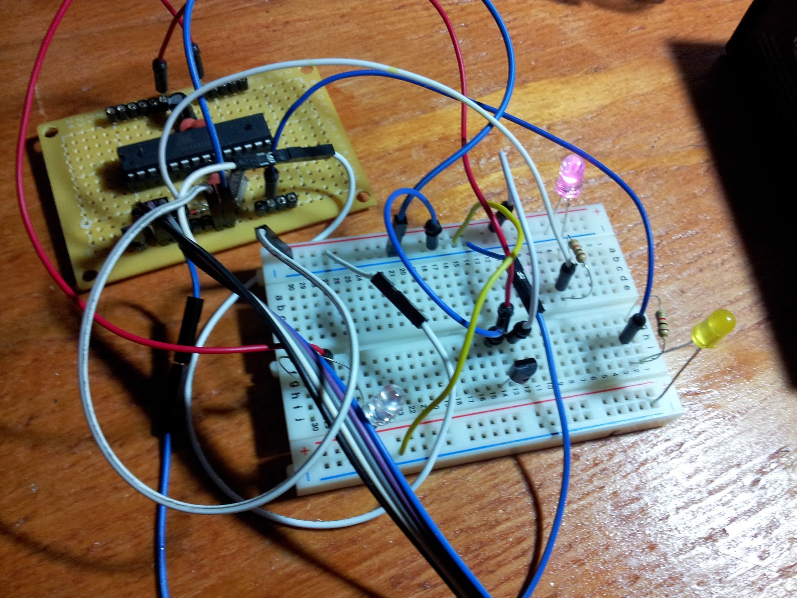
The only components used here besides my Shrimp (Arduino) are:

  • Pink LED
  • Yellow LED
  • LM35 chip
  • 2 resistors of unknown values

I connected the LED's without a resistor and worked fine. They were brighter, but I decided to put something to prevent them from burning out.

My code is the following:


//declare variables
float tempC;
int tempPin = 0;                                      // Where 0 is an analog input
int tempF;

int blueled = 2; //the pink led is connected to digital pin 2
int yellowled = 6; //the yellow led is connected to digital pin 6

int A = 0; // I use A to keep a value stored for the outside temperature in small numbers. At first it is zero
int C = 0; // C also helps defining what the position in the ones is. I will provide example

void setup()
{
Serial.begin(9600);                                //opens serial port, sets data rate to 9600 bps

pinMode(blueled, OUTPUT);
pinMode(yellowled, OUTPUT);

}

void loop()
{
tempC = analogRead(tempPin);           //read the value from the sensor
tempC = (5.0 * tempC * 100.0)/1024.0;  //convert the analog data to temperature
tempF = (tempC*1.8)+32;  //convert celcius to farenheit
Serial.println((byte)tempF);      //send the data to the computer

A = tempF/10;
C = tempF-(A*10);

delay(1000);
for (int i=0; i<(A); i ++)
{
digitalWrite(blueled, HIGH);
delay(800);
digitalWrite(blueled, LOW);
delay(600);
}

for (int n=0; n<( C ); n ++)
{
digitalWrite(yellowled, HIGH);
delay(900);
digitalWrite(yellowled, LOW);
delay(600);
}
delay(5000);
}


This code is what I was able to do without much experience programming. I hope it helps somebody out there.

Why am I using A and C?
These are random variables.
Example: my current temperature is 95F.
I can divide 95 by 10 (95/10 = 9.5) but for some reason arduino thinks its 9.
Now if I multiply  9*10=90. I had my temperature reading as 95, so 95-90=5.
Now I can tell the pink LED to flash 9 times, and the yellow one to flash 5 times.

I also made a video. Its on YouTube:
http://www.youtube.com/watch?v=0R_kQ_yB8_k

The setup of the board is simple. Connect the LM35 to the same ground and power than my shrimp. The middle lead goes to a pin on my shrimp. my led's are grounded with my shrimp and each positive side goes to a pin on my shrimp through a resistor (optional?)

The way it works, as explained on the video is as follows:
For example, if the current temperature is 94 degrees Farenheit (it measures in farenheit), the pink LED will flash nine times, and the orange one will flash four.
Another example: if the current temperature is 112 degrees, the pink led will flash 11 times, and the yellow one will flash 2 times.
OR just count the pink flashes and multiply them by ten, count the yellow flashes and add them together.

Where can you use this system?
If you add a solar panel to it, and a battery, you can have an "unlimited" power supply for a small arduino or even an AtTiny if you can program one. You can set it outdoors and know the outside temperature as you sit outside enjoying the view of the cars drive by.
You can also set it by the window so you know all the time what the current temperature is. Every six seconds. I have learned how to ignore LED's indoors, I dont now about you.

Thursday, January 17, 2013

Building a Shrimp Microcontroller

This is a post created by a brand new fan of Arduino (me). Just today (Jan 17 2013), I started building the shrimp with no idea of what I was doing and I managed to finish it! It is built with the minimum amount of components, but its a start. I have no idea how this shortage of components will affect the programming of the Shrimp, but I'll find out later.

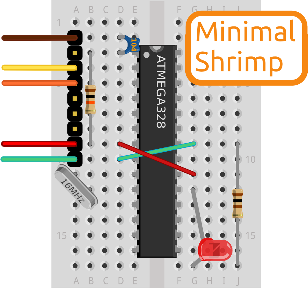
First, we need all of the components shown in this picture taken from the Shrimp website:
The materials used are the following:
(1) CP2102 USB to UART converter (from ebay)
(1) Ceramic capacitor, 100 nF (Also labeled as 104, meaning it is 10 0000 picofarads; this is number 10 plus four zeros after it, making 100,000 picofarads equals to 0.1 uF)
(2) Ceramic capacitor, 22 pF (labeled as 22)
(1) Crystal Oscillator (rated at 16.000 MHZ)
(1) Resistor (rated at 10 Kohm, but I went for the color shown in the pic: brown, black, orange, gold)
(1) Atmega328P-PU (found on ebay, came already with Arduino UNO Bootloader; I know you need to program your Atmega to use it as an arduino, or else its only a piece of plastic)
(3) wires, to make connections

NOTE: In order to test the arduino, I had to connect an LED to it, but I'll show you later.

First I built the Shrimp. I do not know if these ceramic capacitors have a direction, so I just placed them all looking at me, just like in the picture. The crystal oscillator is also sitting just like in the picture. The resistor has not direction whatsoever.
My finished product looks like this:
See that green LED? and the wire going into the negative side of the LED? well, this is what I added in order to test it. the LED is going into D13 and to negative. The yellow wire goes from GND to the LED's negative side.

and the USB to UART converter looks like this:
Note that the brown cable is going into DTR (what looks like J3) but this is because the little board is actually labeled in the back. There, it says DTR. This brown cable is not even soldered, its just touching in there (I'll improve on it later). Also, this brown cable is connected to a yellow one that goes to spot 23 on the breadboard.

After everything was built (except the LED part) I tried to upload a program to the Shrimp. Note that in the shrimp webpage they tell you to use Arduino IDE as the programming tool. Im assuming you cant use the same as the arduino UNO, but im not sure.

After I did all of this, I had the problem where I was not able to upload a simple file to the Shrimp. I was getting the error: avrdude: stk500_getsync(): not in sync: resp=0x30
The Arduino IDE was also trying to connect through COM3. This error could've been due to two reasons: The Atmega328 did not have the Arduino Bootloader installed (as promissed from the ebay seller) or I did not have the drivers for the UART converter. Needless to say, my computer was not recognizing my Shrimp. It would try to install the drivers but could not. Windows tried to help me in every way but failed.

My computer is running Windows Vista, and it didnt have the drivers for the USB to UART converter. I had to go to the webpage and download it (Silicon Labs). The actual link to the driver is the this one.

After installing the driver, the Arduino IDE, when trying to upload the program (by the way, this is the program) was still trying to upload through COM3. After the driver was installed, COM15 was also available, so I switched to it and Arduino IDE uploaded my simple LED program to my Shrimp.

Today I am a happy camper. I hope this is of some use to someone out there.

Update: 07/08/2013
I have soldered the Arduino onto a board and it looks nice. I purchased all of the items from ebay except for the board which I got from my local Radio Shack. I just wanted to show it here. Also, I want to mention that I want to build another one with the board spray painted Arduino blue, and with a little logo or something to make it stand out. I will update it here if I ever do.
Also I want to mention that for being my first time soldering something this complex onto a board, I did a good job!
These are the pictures of the board: