I will provide the code here and pictures of the system.
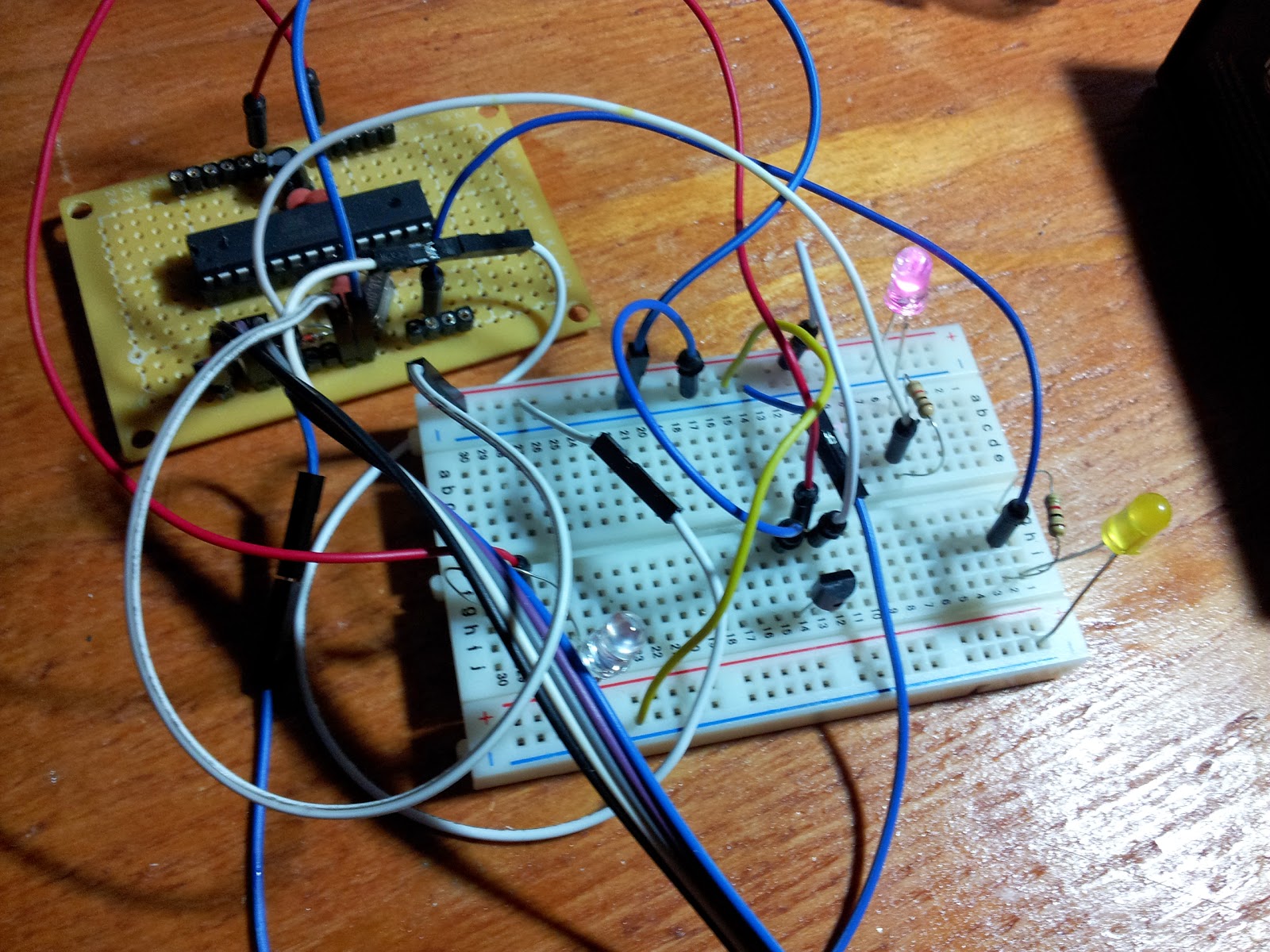
The only components used here besides my Shrimp (Arduino) are:
- Pink LED
- Yellow LED
- LM35 chip
- 2 resistors of unknown values
I connected the LED's without a resistor and worked fine. They were brighter, but I decided to put something to prevent them from burning out.
My code is the following:
//declare variables
float tempC;
int tempPin = 0; // Where 0 is an analog input
int tempF;
int blueled = 2; //the pink led is connected to digital pin 2
int yellowled = 6; //the yellow led is connected to digital pin 6
int A = 0; // I use A to keep a value stored for the outside temperature in small numbers. At first it is zero
int C = 0; // C also helps defining what the position in the ones is. I will provide example
void setup()
{
Serial.begin(9600); //opens serial port, sets data rate to 9600 bps
pinMode(blueled, OUTPUT);
pinMode(yellowled, OUTPUT);
}
void loop()
{
tempC = analogRead(tempPin); //read the value from the sensor
tempC = (5.0 * tempC * 100.0)/1024.0; //convert the analog data to temperature
tempF = (tempC*1.8)+32; //convert celcius to farenheit
Serial.println((byte)tempF); //send the data to the computer
A = tempF/10;
C = tempF-(A*10);
delay(1000);
for (int i=0; i<(A); i ++)
{
digitalWrite(blueled, HIGH);
delay(800);
digitalWrite(blueled, LOW);
delay(600);
}
for (int n=0; n<( C ); n ++)
{
digitalWrite(yellowled, HIGH);
delay(900);
digitalWrite(yellowled, LOW);
delay(600);
}
delay(5000);
}
This code is what I was able to do without much experience programming. I hope it helps somebody out there.
Why am I using A and C?
These are random variables.
Example: my current temperature is 95F.
I can divide 95 by 10 (95/10 = 9.5) but for some reason arduino thinks its 9.
Now if I multiply 9*10=90. I had my temperature reading as 95, so 95-90=5.
Now I can tell the pink LED to flash 9 times, and the yellow one to flash 5 times.
I also made a video. Its on YouTube:
http://www.youtube.com/watch?v=0R_kQ_yB8_k
The setup of the board is simple. Connect the LM35 to the same ground and power than my shrimp. The middle lead goes to a pin on my shrimp. my led's are grounded with my shrimp and each positive side goes to a pin on my shrimp through a resistor (optional?)
The way it works, as explained on the video is as follows:
For example, if the current temperature is 94 degrees Farenheit (it measures in farenheit), the pink LED will flash nine times, and the orange one will flash four.
Another example: if the current temperature is 112 degrees, the pink led will flash 11 times, and the yellow one will flash 2 times.
OR just count the pink flashes and multiply them by ten, count the yellow flashes and add them together.
Where can you use this system?
If you add a solar panel to it, and a battery, you can have an "unlimited" power supply for a small arduino or even an AtTiny if you can program one. You can set it outdoors and know the outside temperature as you sit outside enjoying the view of the cars drive by.
You can also set it by the window so you know all the time what the current temperature is. Every six seconds. I have learned how to ignore LED's indoors, I dont now about you.
No comments:
Post a Comment